Contributions to ICIS’01, to be published in Rev. Sci. Instrum.
S.C.
Jeong, M. Oyaizu, E. Tojyo, H. Kawakami, H. Ishiyama,
H. Miyatake, K. Enomoto, I. Katayama and T. Nomura
IPNS, KEK, 1-1, Oho, Tsukuba, Ibaraki 305-0801, Japan
We have simulated the trajectories of ions injected into an ECR plasma, by taking into account explicitly the cumulative small angle scattering of charged ions as well as the confinement magnetic field of the ECR source. Assuming homogeneous and uniform plasma in a given volume, the stopping efficiency, defined as a probability that the injected ions are alive in the plasma volume until their initial directional motions become at random, has been extracted and discussed.
Recently, many radioactive nuclear beam (RNB) facilities based on an isotope separator on-line (ISOL) have proposed a charge breeding system, which converts the singly charged ions from the ISOL to those of higher charge state for further acceleration. The possibility of an electron cyclotron resonance (ECR) ion source as a charge breeder has been proven experimentally1, by showing that the external injection of ions into an ECR ion source is a very general process for beam production.
For further ionization of the injected ions in the ECR charge breeder, a stopping process is essential. Through the process, the injected ions lose their initial directional motion as well as kinetic energy by ion-plasma collisions. At the end of the process, they can be considered as plasma constituents. If the kinetic energy of ions at the instant of injection is the same order of that of plasma ions, the collisions between ion pairs, i.e. injected ions and plasma ions, are most efficiently happened for the stopping. The time for the stopping is about several tens microseconds under a standard plasma condition of ECR ion sources2. On the other hand, the time required for breeding charge state from 1+ to 2+ ranges over an order of millisecond3. To a good approximation, therefore, the stopping process can be considered as a separate step followed by the subsequent ionization.
The stopping process for externally injected ions in plasma has been well described in Ref. 4. Here, we apply it to the ECR plasma that is confined in a cylindrical volume by the axial and radial magnetic field of the ECR ion source. It should be helpful for better understanding of the process, especially for further development of the ECR charge breeder with a high efficiency. However, it is too complicate to describe the stopping process in the ECR plasma in a very realistic way because of the presence of unknown plasma parameters. Instead, for simplicity, we have simulated the motion of the injected ions in a given volume of the ECR plasma during the stopping process under the following assumptions. (1) The plasma is homogenous and uniformly distributed over the volume with a density of 5x10¹¹ / cm3. (2) The temperature of plasma ions is 1 eV. (3) The incident energy of injected ions is 10 eV known as the energy acceptance of the ECR plasma1. Finally, we have extracted the stopping efficiency, by counting the ions moving in the plasma volume without splats by the end of the stopping process.
II. THE SIMULATIONS
We first consider that a cloud of ions initially concentrated at a point in velocity space is incident on a plasma of a single kind of ions of a specific charge state. The velocity distribution of the plasma ions is assumed to be Maxwellian of a temperature Ti. Since the comprehensive description of the collision processes of ion-ion pairs can be found in Refs. 4, we just give two expressions that allow us to describe the evolution of the cloud of incident ions as a whole in velocity space at any instant of time; the average energy loss rate and the average deflection rate of velocity. The latter is associated with the rate of expansion of velocity in transversal directions.
The rate of energy loss is given by
d<E> / dt = - E / tel, (1)
and the deflection rate of velocity is given by
d<(DV⊥ )2 > / dt = V2 / tD , (2)
where tel and tD are the relaxation times of the energy loss rate and deflection rate, respectively. The respective relaxation time is a function of the incident energy of the injected ions, plasma density, plasma temperature and masses of colliding partners, as shown in Refs. 4.
Using the above expressions, the energy loss and transversal velocity spread of the ions as a result of the collisions during a certain time step were calculated, by using the value of energy of one time step before. Here, we assume an axially symmetric collision; the collision occurs always along the incident direction of the ions at any instant of time. According to the residual energy and the dispersion in the velocity space calculated in this way, the velocity of an ion of interest in all directions at a time was calculated by the Monte-Carlo method.
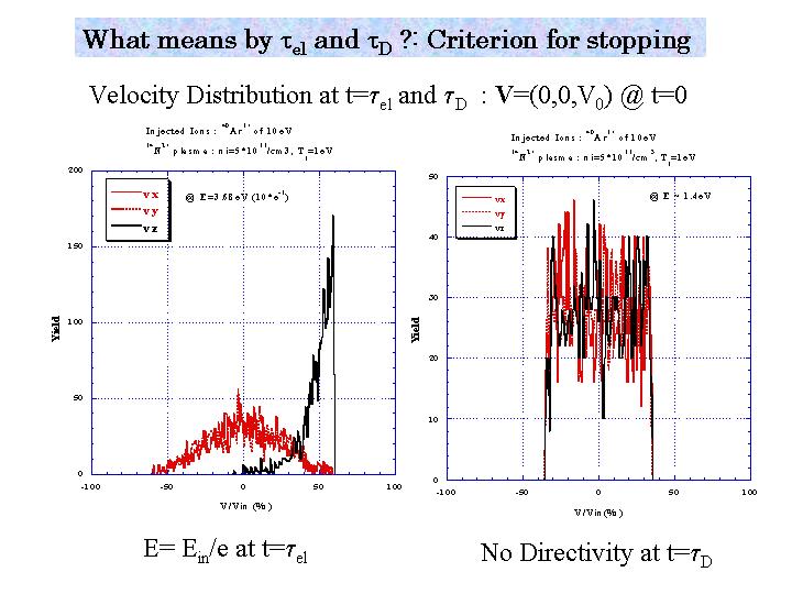
Fig.1 Velocity distributions obtained after a unit of relaxation time: after a tel (left panel) and a tD (right panel). The ions with a fixed velocity were injected along the z-axis at t=0. Normalized by the initial velocity, three components of velocity are presented.
In Fig.1, the velocity distributions are shown after a time of tel and tD, respectively. Ar1+ ions of 10eV were injected into the plasma containing N2+ ions with the density of 5x10¹¹/cm3 and the temperature of 1eV. These velocity distributions were obtained for 1000 test particles. After a tel, the kinetic energy is reduced to 1/e times of the initial and there remains a longitudinal translational motion on the average. After a tD, however, the velocity distributions of three components become identical, which means that three directional motions are equally probable. This is our criterion for stopping, necessary condition that the injected ions are captured and then can be charge breeded. In this case, the kinetic energy of Ar1+ ions was about 1.4eV (~1.5 times plasma ion temperature). This value is the lower limit such that a flux of test particles could heat the plasma, whereas a flux of slower particles than the limit will cool the plasma.
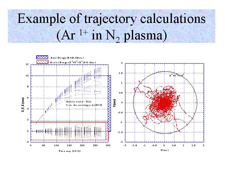
Fig.2 Trajectories of Ar1+ ions in the N2+ plasma: Three components of the positions as a function of time are presented (Left). The plasma volume under consideration is shown as a hatched area, both in the radial and axial directions. The ions started from the origin along the z-axis. In the right panel, the radial trajectories are presented
In order to take into account simultaneously the change in the velocity due to the collisions as well as those due to the magnetic field at each time step, we have introduced an artificial electric field causing the change in the velocity by scatterings. We calculated the trajectories of the ions under the electro-magnetic field, by referring to the method in Refs. 5. We have chosen the magnetic field configuration of the ion source used as a charge breeder in our test bench 6,7. The axial length between two maxima of the axial field is 100mm and the diameter of the cylindrical plasma chamber is 32mm. This is the plasma volume of interest. An example of the trajectory calculations is presented in Fig.2, showing a bunch of trajectories of Ar1+ ions injected along the axis of the plasma chamber (z-axis) into the ECR plasma containing N2+ ions. The initial position was (x, y, z) = (0, 0, 0), where the axial magnetic field is maximum. The calculation was stopped when the residual energy was equal to 1.5 eV after about a half of a tD because the motions, equally probable in all directions, were observed with the help of the magnetic field if the ions passed through almost all the axial length of the plasma.
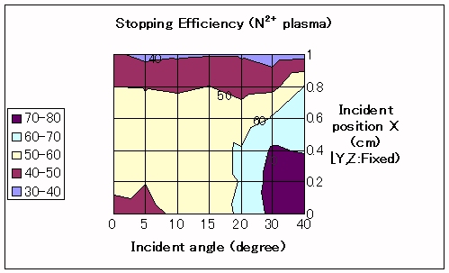
Fig.3 Contour plot of the stopping efficiencies for Ar1+ ions of 10eV injected into the N2+ plasma with various injection conditions; different incident angles and positions. The positions represent the off-axis distance along the x-direction. The other two components, Y and Z, are fixed to zero.
As shown in Fig. 2, a large fraction of incident ions are outside of the plasma volume at the end of the calculation. By removing these ions from the incident flux of ions, we extracted the stopping efficiency for the ions of the ECR plasma currently considered. As shown in Fig. 2 (upper panel), the axial loss is dominant in the case of N2+ plasma, and the stopping efficiency is about 50% when ions are incident on and along the symmetry axis of the plasma. For the plasma containing N3+ ions, almost all the injected ions are stopped around the center, 4cm distant from the incident position, with a radial loss of a few %. It should be noted that there exists some directivity in the motions of ions because the calculations stop when E = 1.5 eV, as discussed above.
The stopping efficiencies vary according to the incident conditions of ions; different incident angles and off-axis injection positions. For the off-axis positions less than 4mm, larger incident angles are favorable; the efficiency reaches 75% even in the N2+ plasma. With increasing off-axis positions more than the above, the stopping efficiency decreases as shown in Fig.3 due to the increased fraction of the radial loss.
IV. CONCLUSION
In summary, we have extracted the stopping efficiency for Ar ions with various injection conditions by a simple model under a given condition of the plasma containing N2+ ions. It is straightforward to apply this calculation to other situations. In the present model, we have assumed a homogeneous and uniform distribution of plasma over the cylindrical plasma volume (f32mm x 100mm). The present simulation reveals that such a plasma volume is necessary in order to capture the ions with a high efficiency.
References
[1] N. Chauvin et al., Nucl. Instrum. Methods A419, 185 (1998)
[2] R. Geller, Electron Cyclotron Resonance Ion Sources and ECR plasmas, Bristol and Philadelphia: Institute of Physics Publishing, 1996
[3] H. I. West, Intern. Rep. UCRL-53391, Lawrence Livermore Natl. Lab., 1982
[4] B.A. Trubnikov, Rev. of Plasma Physics Vol.1, 105 (1965)
[5] J. Vamosi and S. Biri, Com. Phys. Commun. 98, 215 (1996)
[6] M. Oyaizu et al., Rev. Sci. Instrum. 71, 113 (2000)
[7] M. Oyaizu et al., Rev. Sci. Instrum. (this proceedings)
![]()
![]()