Contributions to ICIS’01, to be published in Rev. Sci. Instrum.
The development of a charge breeding system with ECR ion sources of permanent magnets
M. Oyaizu, S.C. Jeong, E. Tojyo, H. Kawakami, H. Ishiyama, H. Miyatake, K. Enomoto, I. Katayama and T. Nomura
IPNS, KEK, 1-1, Oho, Tsukuba, Ibaraki 305-0801, Japan
For the construction of an ECR charge breeder at KEK-JAERI radioactive nuclear beam facility, we have made and tested a pilot charge breeding system consisting of two compact-sized ECR ion sources. Using a simulation code, we have investigated the geometrical beam acceptance of the present system for the external injection of ions of interest into ECR plasma. Following the discussions on the ECR plasma influenced by a deceleration potential for the external injection, the charge breeding efficiency for Ar ions is presented and discussed.
At KEK-JAERI radioactive nuclear beam facility1, a charge breeding system employing an electron cyclotron resonance (ECR) ion source as a charge breeder, is going to be built for converting singly charged radioactive ions from an isotope separator on line (ISOL) to more highly charged ions with A/q<7 (mass to charge ratio of ions) for further acceleration. In order to study the external injection of singly charged ions into the ECR charge breeder and provide some insights for the design, we have made a pilot charge breeding system, by using two existing ECR ion sources fully made of permanent magnets. The details of those sources can be found in Refs. 2. Especially, we have newly made a deceleration system that allows a step-by-step deceleration of ions during their injection into the ECR charge breeder as well as a sudden deceleration adopted in Refs. 3.
After a brief description of the deceleration system, the beam acceptance of the present system for the external injection will be presented, as a result of the simulation by SIMION74. Under the presence of the deceleration electrode inserted close to the ECR plasma, the variations of the charge state distribution of the ions extracted from the charge breeder will be presented. In addition, the observed charge breeding efficiency will be discussed.
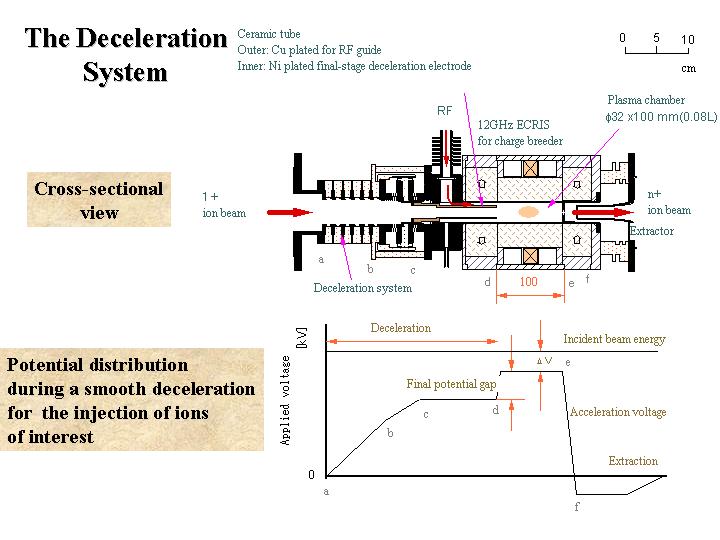
II. THE DECELERATION SYSTEM
Ar1+ ion beam of 12 keV was produced by a 2.45GHz ECR ion source. After being analyzed by a 45o magnetic separator, the beam was characterized by a double slit located at the focal point of the separator. Properly shaped and decelerated by the following beam optical system, the beam was injected into a 12GHz ECR ion source for further ionization.
The optical system for deceleration consists of an einzel lens doublet and a series of deceleration electrodes to make a step-by-step deceleration possible. Five ring-shaped electrodes upstream are connected with each other in series through resisters, which can provide a smooth potential barrier for deceleration, as shown in Fig. 1. As a final stage of deceleration, a cylindrical electrode, 150mm long, is inserted axially into the plasma chamber of the source. The inner diameter of the cylindrical electrode is reduced to 16mm inside the plasma chamber, and it reaches the position having a maximum value of the axial magnetic field. The plasma volume of the charge breeder is 0.08L, 32mm in diameter and 100mm in axial length.
With this geometry, we have performed beam optics calculations in order to investigate the geometrical beam acceptance of the present charge breeder, by using SIMION7. An axial symmetric coordinate system with a mesh size of 1mm was used in the calculations. For more realistic calculations, a plane plasma meniscus and the axial magnetic field of the ECR charge breeder were taken into account. Ar1+ ions of 12 +DV keV starting from the position of the slit with different off-axis positions and angles, enter the region for deceleration as shown in Fig. 1.
The value of DV corresponding to the difference in the potentials actually applied to two ion sources, permits tuning the final energy of 1+ ions at the instant of injection. During the calculations, a fixed value for DV of 10eV was used3,5. Depending on the incident angles, a fraction of ions rebounded from the plasma meniscus. By counting the ions successfully injected into the ECR charge breeder, we estimated the beam acceptance of the present system for the ions of interest. In Fig. 2 compared are the acceptances in terms of a beam emittance obtained by two types of deceleration. During a smooth deceleration, the ions are smoothly decelerated to 10keV and then fully decelerated before injection by the potential difference (final potential gap in Fig. 1) between the cylindrical electrode and the plasma meniscus, while the ions are suddenly decelerated around the meniscus in another case. In the latter case, the final potential gap equals to 12kV in Fig.1. The beam emittance at the focal plane of the 1st separator (lower panel in Fig.2) corresponds to the actual beam acceptance of the present system. Slightly better acceptance is expected in the case of the sudden deceleration. In an ideal case just depending on the type of deceleration, independent of the optics upstream, clear differences in the acceptance were obtained, as shown in the upper panel of Fig.2. Smaller potential gap during the final stage of deceleration is favorable for injection. In the present system, however, a large reduction of the ideal acceptance is expected during the smooth deceleration, whereas the ideal beam acceptance is almost the same as the actual one during the sudden deceleration. In order to improve the actual beam acceptance in the case of the smooth deceleration, the size and the structure of the entrance of the final stage electrode shown in Fig.1, should be modified.
The extent of the potential difference also influences the charge state distribution of the extracted ions, well known as a biased probe method for the production of highly charged ions. In Fig. 3, the charge state distributions of Ar are compared for different values of the potential negatively applied to the final stage electrode relative to that of the charge breeder. With increasing potential difference, the intensity of ions of higher charge state enhances, whereas the total beam intensity of Ar ions is almost constant. It should be noted that the present values of the applied potential are almost an order of magnitude larger than those usually adopted by the biased probe method. When the potential difference exceeding 4kV in the present case, the plasma discharge was observed to cease. The critical value of the potential difference depends on the plasma density, i.e. the gas pressure in the source and also on the position of the electrode. The electric field caused by the potential appears not to be well shielded and consequently disturbs the ECR plasma. It might be due to the small volume of the charge breeder and the large diameter of the electrode. In the following, we fixed the potential by 2 kV.
III. THE CHARGE BREEDING EFFICIENCY
The ECR plasma of the charge breeder was made by a support gas, N2, and a typical charge state distribution is shown in Fig. 4. The Ar1+ ions, with an intensity of 1mA and an emittance of 40p mmmrad, was injected into the plasma after fully decelerated. The Ar ions are extracted again and their charge distribution was measured. In Fig. 5 are shown the charge distributions of Ar ions resulting from the external injection of Ar1+ ions of 1mA, and of pre-existing Ar ions as a background. The charge distribution associated with the injected ions shows an enhanced fraction of 1+ ions, possibly corresponding to ions extracted as it is without charge breeding. It reflects the fact such that the injected ions could not stop fully in the plasma shown in Fig. 4 as pointed out in Refs. 5. There is also an enhancement in the yields of higher charge state, manifesting itself in the charge breeding. This observation, however, is not stable, strongly depending on the plasma density. If the plasma intensity increased by a factor of three, for example, such enhancement did not show up. The breeding efficiency in total, sum of specific efficiencies from 2+ to 8+, was at most 16%, and the efficiency for 5+ or 6+ Ar ions was around 2%. We have recently obtained similar results by the injection of metallic ions, Fe. In this case, however, we observed that the breeding efficiency is quite sensitive to the value of DV as shown in Refs. 3. In the present case, we obtained best results when DV was equal to zero. We observed also similar results with the beam intensity of 2mA and the beam emittance of ~140p mmmrad.
References
[1] H. Miyatake et al., Proceedings of 5th international
conference on radioactive nuclear beams, 3-8 April, 2000,
Divonne (France)
[2] M. Oyaizu et al., Rev. Sci. Instrum. 71, 1113 (2000)
[3] N. Chauvin et al., Nucl. Instrum. Methods A419,
185 (1998)
[4] SIMION 3D version 7.0 by David A. Dahl, INEEL,
Idaho Falls, ID83415
[5] S.C. Jeong et al., Rev. Sci. Instrum. (this proceedings)
Fig.1 Cross-sectional view of the deceleration system and potential
distribution applied during a smooth deceleration for injection.
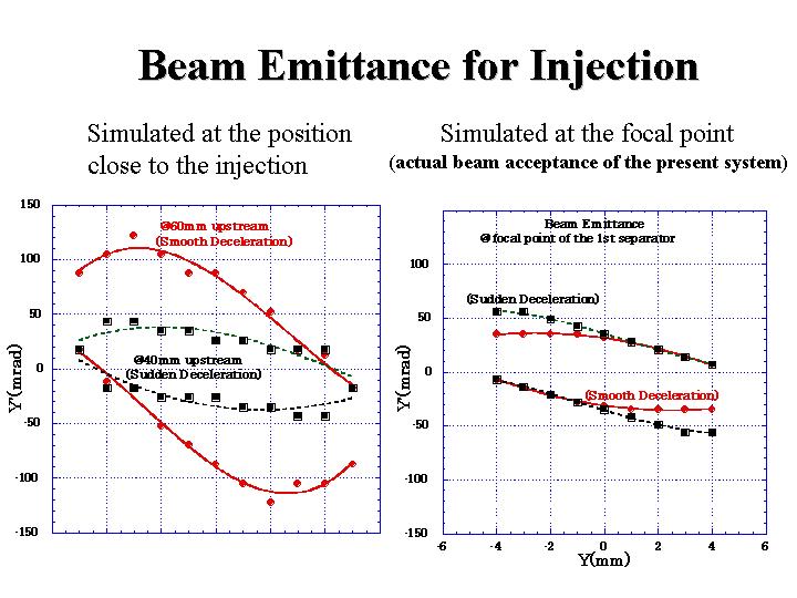
Fig.2 Expected beam acceptance for the injection at the starting position of Ar 1+ ions
in the calculation.
The ions were generated at a given position with varying off-axis positions (Y) and
angles(Y’). Two types of deceleration, the smooth and sudden decelerations, are
compared. The final energy of the ions in the charge breeder was fixed to 10eV.
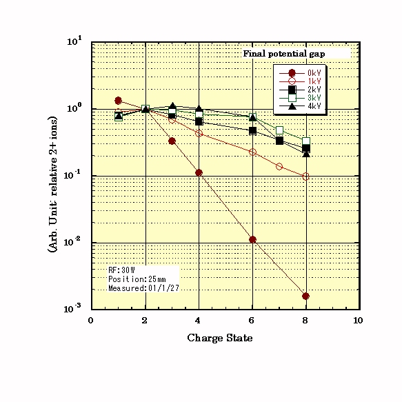
Fig.3 Charge distributions
of Ar ions for various values of the potential applied to the final-stage electrode 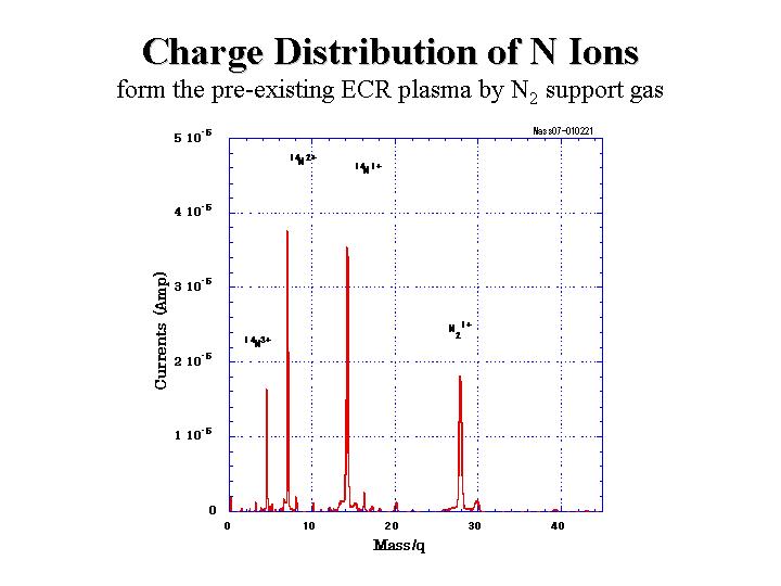
Fig.4 Mass spectrum of the ions extracted from the charge breeder by feeding a support gas, N2.
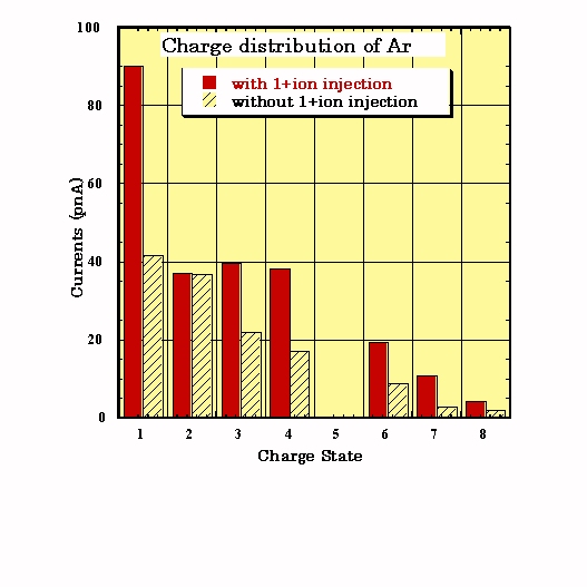
Fig.5 Charge distributions (in a uint of pnA) of Ar ions. Respectively presented are two distributions resulting from the external injection of Ar1+ ions of 1mA and of the pre-existing Ar ions in the ECR charge breeder.
![]()